Hydraulic accumulator
The main task of an accumulator to take a specific amount of fluid under pressure from the hydraulic system and store it until it is required within the system.
As the fluid is under pressure, accumulators are treated as pressure vwssels and must be designed taking into account the maxoperaing pressure.
However, they must also pass the accepatance standards in the country in which they are being used.
In order to store energy in accumulators, the fluid in an accumulator is weight or spring loaded or pressurised by a gas.
The refore a balance is maintained between the pressure in a fluid and the opposmg pressure produced by the weight, spring or pressure created lrom the gas. Weight and sprig loaded accumulators are only consrdered ior specral industrial applications and hence are oi little Imponance. Gas pressurised accumulators without a separating element are seldom used in hydraulic systems due to the fluid taking in gas.
Depending on the type at separating element used. Piston and membrane accumulators. These accumulators Will be described in more detail in the followrng sections.
The following types of accumulators with separating elements are used in hydraulic systems:
- bladder accumulator
- membrane accumulator
- piston accumulator
Functions of hydraulic accumulators
Hydraulic accumulators have to carry out various funcllons in a hydraulic syslem:
- Fluid resarve
- Energy storage
- Emergency operatron
- Balance of forces
- Compensanon of leakage oil
- Damping of mechanical and prssure shocks
- Damping of pulses
- Vehlcle suspenionon
- Reclaiming ol decelerallon energy accumulalor
- Maintaining constant pressure
- Compensation of flow
Bladder accumulators
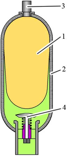
The design of a bladder accumulator is shown in the following figure.

Basic elements of a bladder accumulator:
- accumulator bladder
- pressure container
- valve for gas input
- valve for oil inlet
Membrane accumulators
There are two types of membrane hydraulic accumulator available:
- welded construction
- screwed construction
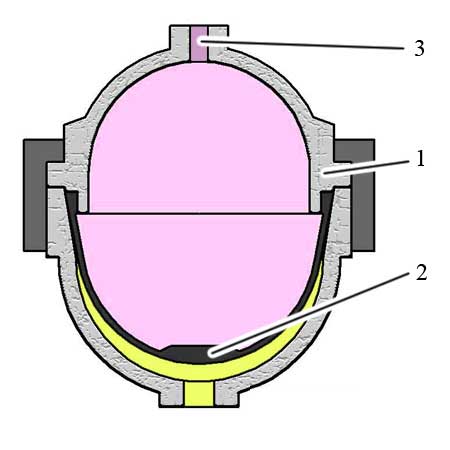
In the screwed construction the membrane is held in position by screwing the top and bottom part to clamping nuts.
In the welded construction the membrane is pressed into the lower pert before the circular seam welding is carried out.
Basic elements of a membrane accumilator

- pressure container
- membrane with valve plate
- gas fill scrow
Piston accumulators
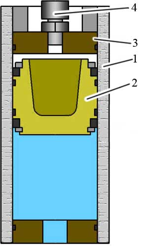
Piston accumulators comrise fluid and gas compartments with a piston being used as the gasting separating element.
The design of a piston accumulator is shown in the following figure.

- cylinder tube
- piston with sealing system
- front covers
- gas port