How to read hydraulic circuits
Information about the device of the hydraulic system is shown on the hydraulic diagram using symbols.
Hydraulics schematic symbols are a basic component of hydraulic circuit. Symbols for hydraulic systems are for functional interpretation and comprise one or more function symbols. Hydraulic symbols are neither dimensioned nor specified for any particular position.
The following list is contains hydraulic schematic symbols to DIN ISO 1219. This list is designed as ad aid for creating symbols.
What symbols represent hydraulic components?
Pipelines
Pipelines on hydraulic circuits are shown with lines connecting the elements.

The control lines are represented by a dotted line.

The direction of fluid flow is indicated by arrows, if necessary. Some lines are designated by letters:
- P - pressure line,
- T - line drain,
- X - control line
- l - drainage.
The connection lines are shown by a shaded point.
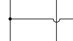
If the lines intersect in the diagram but are not connected, then an arc is drawn at the intersection point.
Tank
Hydraulic fluid is placed in the tank. The tank connected to the atmosphere is shown on the hydraulic circuit.

A closed tank, such as a hydroaccumulator, is shown as a closed loop.

Filter
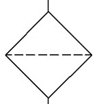
The filter is depicted in the form of a rhomb with a dotted line. This is the line that symbolizes the filter element.
Pump
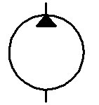
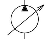
The symbol for the pump is the circle within which a filled triangle (arrow) is drawn. This triangle shows the direction of movement of the fluid. pumps are indicated by a circle, with a triangle arrow indicating the direction of fluid flow.
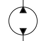
If the pump shows two triangles, then this is a reversible pump.
If the pump symbol has an arrow drawn diagonally, then this is a variable pump.
Hydraulic motor
The hydraulic motor symbol is similar to a pump symbol. The triangle inside the contour is rotated 180 degrees. Triangle shows the direction of supply of fluid to the hydraulic motor. In this case, the arrow indicates the direction of supply of fluid to the hydralic motor.
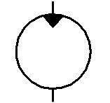
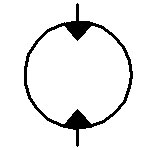
If the symbol shows two triangles, it is a reversible hydraulic motor.
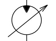
If the arrow is diagonally drawn on the symbol, then it is a variable hydraulic motor.
Hydraulic cylinder
A hydraulic cylinder is a mechanical actuator, that is used to give a unidirectional force through a unidirectional stroke.
On the double-acting hydraulic cylinder symbol, lines of fluid supply to the piston and rod cavity are shown.
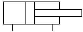
A hydraulic cylinder with a plunger (single acting) is shown as:

Directional valves
To denote a directional valve, several squares are drawn. Each square symbolizes 1 position of the spool. If a directional valve has two positions, then two squares are drawn. The drawn lines in each square show which channels are connected in this position.
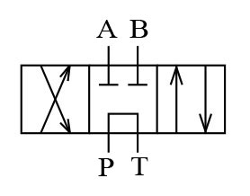
Here four linear (four lines A, B, P, T lines), three positional (three squares) directional valve are shown.
The circuit shows the neutral position of the valve spool. In this example, in the neutral position of the directional valve, the channels P and T are interconnected, A and B are muted.
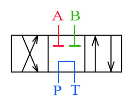
The directional valve can switch by connecting other channels.
On the square to the left, it is shown that when the valve switches, the lines P and B, A and T will connect. This conclusion can be made by virtually moving the directional valve to the right.
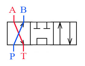
On the square on the right, it is shown that when the directional valve switches to another position, the lines P and A, B and T will connect.
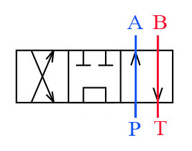
The operation of the directional valve is shown in the video.
Operational modes
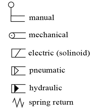
To switch the valve, you need to move the spool. This can be done in various ways.
Types of operation:
- manual,
- mechanical,
- hydraulic,
- pneumatic,
- electric (solinoid),
- spring return.
Controls are shown using symbols.
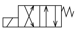
The circuit shows a four linear, two-position valve, with electromagnetic control and spring return.
Pressure relif valve
The figure shows the symbol of the pressure relif valvee.
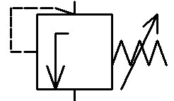
The arrow inside the square indicates the direction of flow of the fluid.
The spring force should be higher and the valve will open.
Check Valve
The check valve allows fluid to flow in one direction, and shut off its flow in the opposite direction. This is also shown in the circuit.

When the liquid flows from top to bottom, the ball (circle) will slide from the saddle, indicated by two lines.
When the fluid flows from below - upward, the ball will press against the saddle, and will not allow the fluid to flow in this direction.
The symbol of the check valve may depict a spring that presses the ball to the saddle.
Throttle
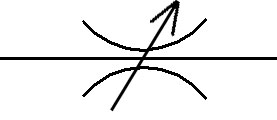
Hydraulic resistance or unregulated choke on the circuit depict two curved lines.
Possibility of regulation, is shown by an arrow. Adjustable throttle is designated as:
Measuring devices
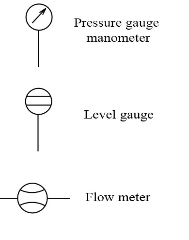
In hydraulic systems, instruments are used: pressure gauge, flow meter, level indicator, their designation of these devices is shown below. Pressure gauge (manometer), flow meter, level gauge.
Hydraulic schematic symbols to DIN ISO 1219
| Main line |
 |
| Control line Drain line |
 |
Energy transfer and storage
| Pump |  |
| Hydraulic motor 1 direction to flow |
 |
| Motor 2 direction to flow |  |
| Accumulator |
 |
| Hydraulic cylinder Double acting |  |
| Hydraulic cylinder Single acting | 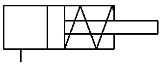 |
Directional valves
| 2/2 way directional valve |
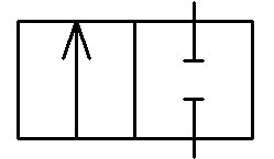 |
| 3/2 way valve | 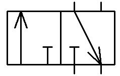 |
| 4/2 way valve | 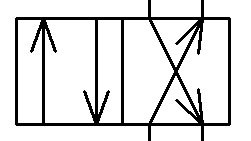 |
| 5/2 way valve |
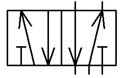 |
| 4/3 way valve |
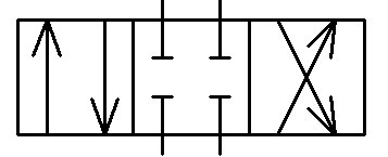 |
Pressure control valve
| Pressure relief valve |
 |
| Pressure reucing valve | 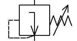 |
Flow control valve
| Throttle valve |  |
| Flow control valve 2 way | 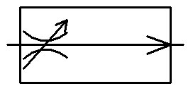 |