What is a Hydraulic Jack?
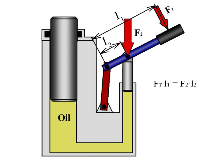
The more than tenfold increase in force produced by the hydraulic jack is sustained by the hydraulic lever principle.
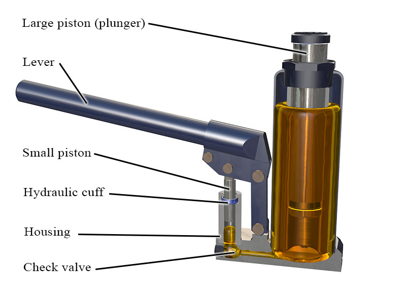
Bottle jack design

The most common elements:
- piston,
- plunger,
- lever arm,
- check valve,
- body.

Lever is positioned in such a way that the arm between the pump’s plunger and the axis is smaller than the arm between the axis and the handle to which the force is applied. In this case the mechanical lever principle is utilized, which allows to magnify the applied force several times.
How hydraulic jacks work

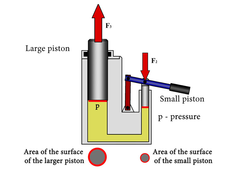
With the help of a mechanical lever, a force is applied to the small piston, making it move downwards. The pressure under the piston will be calculated as the ratio of this force to the area of the surface of the piston. According to the laws of hydrostatics, the pressure applied to the surface of a liquid is transmitted equally in all directions to all points of this liquid.
This means that the same pressure will act on the large piston.
The pressure under both pistons is the same, but the area of the surface of the larger piston is larger, therefore it can assume a larger force.
The larger the area of piston (plunger), and the smaller the area of piston ONE, the greater the amplification factor that can be obtained by using the hydraulic lever is. The total displacement of the large piston will depend on the volume of fluid displaced by the small piston.
The area of the surface of the second piston is larger; therefore the distance it is displaced by will be less than the distance that the first piston was displaced by.
The check valves allow fluid to flow in one direction and do not allow it to flow in the opposite direction.
Now when we pull the handle upwards, the small piston will move upwards as well. The volume of the space underneath it will begin to increase and the pressure will drop. Valve ONE will let fluid out of the tank and into the space under the small piston.
Valve 2 is installed in such a way that it does not allow fluid to flow out from its place under plunger.
When the small piston reaches the top, we will begin to put pressure on the lever again. Valve 1 will not let fluid into the tank, and valve 2 will allow fluid from under the small piston to flow into the space under the large piston, which will move up a little more.
This cycle can be repeated many times: the lever is moved up and the cavity under the pump’s plunger is filled, the lever is moved down and the liquid is forced out into the space under the large plunger. If the load needs to be lowered, the release valve is opened and the large plunger moves downward under the effect of the load’s mass, while the liquid from under it goes into the tank.