How does a gear pump work?
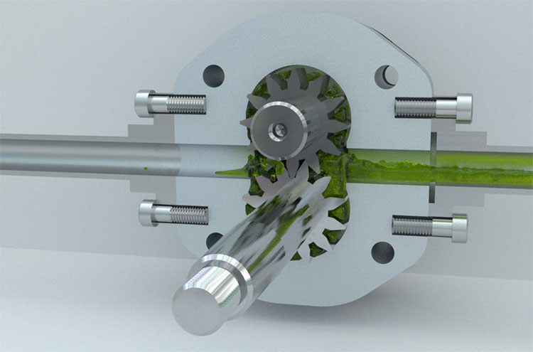
In a gear pump, the meshing of gears is used to pump fluid.
The gears are located within the housing of the pump. One of the gears is the drive gear; it is connected to the engine or drive. The second gear is the driven gear.
When the gear teeth come out of mesh, additional volume is formed. And when they go into mesh, this volume decreases.
The area where the gear teeth come out of mesh will be connected to the suction line. And the area where the gear teeth go into mesh will be connected to the discharge line.
When the gear teeth come out of mesh, the volume of the chamber increases and the pressure inside this chamber becomes lower than atmospheric pressure. Fluid from the tank enters the pump and fills the space between the gear teeth and the housing.

As the gears rotate, the fluid flows along the perimeter to the discharge area, where the gear teeth go into mesh once again. At this point, the chamber volume decreases and the fluid is forced into the pumps discharge channel. It is important to understand that the fluid in the gear pump does not flow through the mesh. It cannot do so, as the gaps in the mesh are very small. The fluid moves along the perimeter of the gears, filling the depressions between the gear teeth.
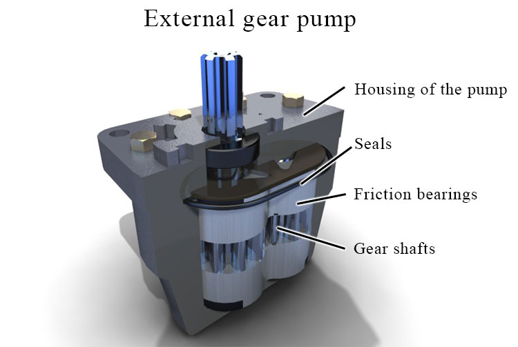
External gear pumps

The housing of the pump contains friction bearings. These bearings have grooves to provide for the lubrication of rotating parts, as well as to direct any leaks to the suction area. The bearings are fitted with gear shafts.
There are seals to ensure the leakproof separation of the suction and discharge channels. The front and back covers are bolted to the housing. The shaft sleeve and the rubber rings prevent fluid from flowing out of the pump.
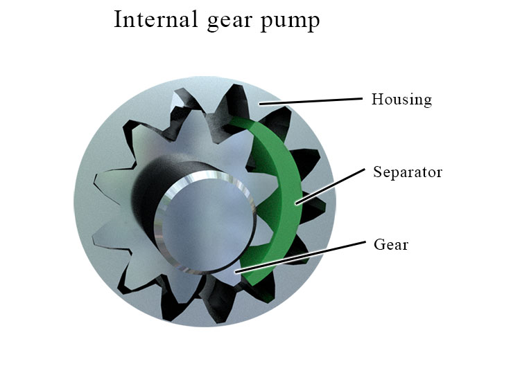
Internal gear pumps
Gear pumps can have not only external, but also internal gearing. Lets take a closer look at how an internal gear pump functions.

The suction channel is located at the point where the gear teeth come out of mesh, and the discharge channel is located at the point where they go into mesh. A crescent-shaped seal ensures the suction area is separated from the discharge area. Without this , fluid will simply keep on flowing inside the pump.
When the gear teeth come out of mesh, fluid fills the space between them. As the gear teeth rotate further, the fluid is delivered to the area where the gear teeth go into mesh. From there, it will be forced into the discharge channel.
Internal gear pumps work more smoothly than external gear pumps, but they are also more expensive due to the higher complexity of their manufacturing process.
Gear Pump Operation
- Bearing wear. The material of the gears is harder than that of the bearings, and so the bearings will wear out faster during operation. Bearing wear can cause increased leaks inside the housing.
- Shaft sleeve wear. Oil will flow out through a damaged shaft sleeve.
- If the seals become damaged, fluid may begin to flow from the discharge area to the suction area. This will cause a reduction in the working pressure and supply.