Fluid coupling and torque converter
A fluid coupling and torque converter are hydrodynamic devices as they both use fluid to transmit rotating mechanical power.
Hydrodynamic transmission
Take a centrifugal pump as an example, fill its housing with water and power the drive motor. As the impeller rotates, the blades will act on the liquid particles, transferring energy to them. The liquid particles will move around the circumference and move from the centre to the perimeter, entering first into the volute and then into the discharge nozzle.
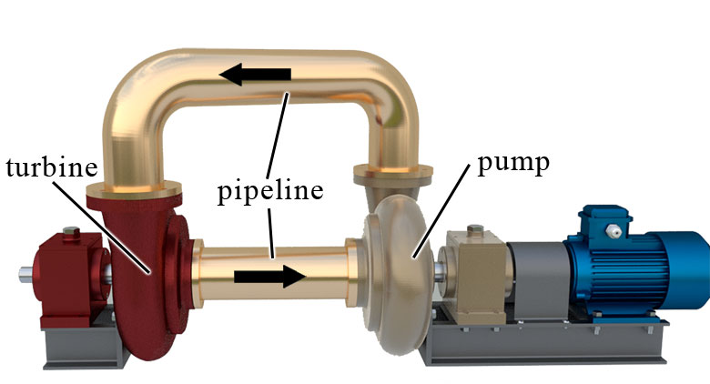
The discharge nozzle is connected to another hydraulic device, a turbine. Its construction is similar to that of a pump, but the turbine performs the opposite task. While the rotating impeller makes the liquid move in a pump, in a turbine, on the contrary, the moving liquid makes the impeller rotate.
The liquid particles entering the turbine housing act on the blades of the impeller, making it rotate. The velocity of the particles decreases. They move from the perimeter to the centre, reaching the outlet. A hydrodynamic transmission is created by connecting the turbine outlet to the pump suction, which can transfer the rotation from the pump inlet shaft to the turbine outlet shaft. There is no rigid mechanical connection between the shafts and the energy transfers through the liquid.
Fluid coupling
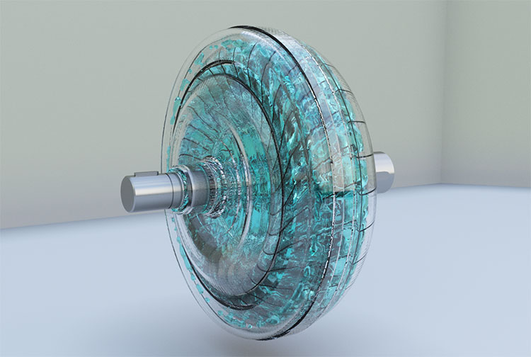
The impeller and turbine and the liquid retaining casings are the main components of the device shown. Pipelines are only needed to bring the liquid from one wheel to the other. Let us try to get rid of them, as they cause additional resistance.
If two wheels, impeller and turbine, are mounted in the standard casing, you get a fluid coupling.
Fluid coupling design
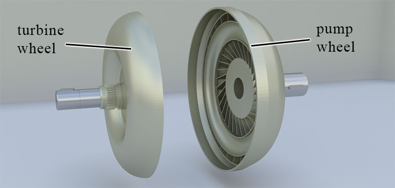
The main elements of the fluid coupling:
- pump wheel,
- turbine wheel,
- housing.
Fill the casing with liquid and start turning the inlet shaft on which the pump impeller is fixed. The impeller blades will act on the liquid particles. They will rotate with the blades and move from the centre to the perimeter. The impeller is made so that the accelerated particles will be ejected from it. These particles hit the turbine and make it rotate, while the output shaft connected to the turbine rotates as well. The particles are slowed down and moved towards the centre of the wheel, where they are sucked back in by the pump. The liquid runs from the impeller to the turbine along the perimeter and from the turbine to the impeller in the centre. In this way, the rotation is transferred from the inlet to the outlet shaft, but a liquid rather than mechanical transmission is used.
Such transmission provides slipping, infinitely variable rotation frequency, the possibility of stopping the outlet shaft when the inlet one rotates, limitation of dynamic overloads, and smoothing shocks when transmitting torque.
Torque converter
The fluid coupling enables torque to be transmitted without any change, except for energy loss. Moreover, a torque converter, like a gearbox, can change the torque. For this purpose, a reactor is installed between the impeller and turbine in the torque converter, which ensures a spiral effect that affects the transmission characteristics.
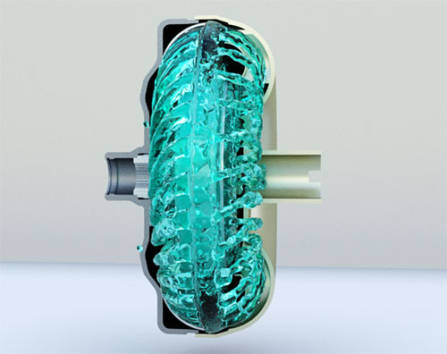
In the converter, as in the fluid coupling, the liquid is pressurised by the impeller and flows to the turbine, causing it to rotate. In the converter, however, the reactor is placed between the impeller and turbine. In the torque converter shown, the liquid flows from the turbine outlet to the reactor, which ensures that the flow is swirled in the direction of rotation of the pump, resulting in more torque.
Torque converter design
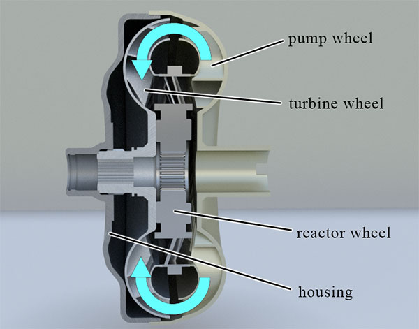
The main elements of the torque converter:
- pump wheel,
- reactor wheel,
- turbine wheel,
- housing.
How does the reactor change torque?
The liquid particles at the outlet of the pump perform a complex movement. On one side, they move from the impeller to the turbine. On the other side, they rotate about the axis of rotation of the wheels. It is the second component that affects the torque.
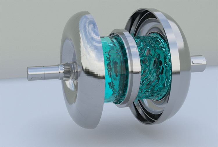
The reactor, which is mounted at the outlet of the turbine, spins the flow towards the rotation of the pump impeller—increasing both the rotation of the particles around the central axis and torque.
To increase the efficiency of torque converters, impeller and turbine locking mechanisms, free-wheel clutches that can be activated depending on the speed or speed ratio of the engine and gear, such mechanisms are used in torque converters in automatic car transmissions.